
AMBB Breakout Board
A 3D-printed, solderless adapter that lets an 8-SOIC surface-mount chip plug into a breadboard or perfboard like a DIP part. The adapter holds right-angle header pins against the chip’s leads. It reuses the chip and the printed parts, and needs no soldering and no PCB.
It was published as Brooks, Peplinski and Pearce (2023), below. This repository holds the design files, print projects and analysis from that paper, which were first published on the Open Science Framework, https://osf.io/dh6uy/.
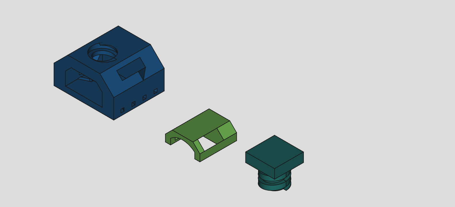

How it works
Section titled “How it works”Three printed parts and eight header pins make one adapter:
- Enclosure (11 x 13 x 8.25 mm): a main cavity, eight angled channels that guide the header pins down to breadboard pitch, and a threaded hole in the top. Two pockets in the sides take multimeter probes, to check contact between the chip’s leads and the pins. Two slots in the floor reduce print artifacts at the ends of the channels and show whether the pins sit right in them.
- Component housing: carries the chip, with a slot for each lead and pockets of its own for the probes, and slides into the enclosure’s cavity along a track.
- Bolt: screws into the enclosure and clamps the housing down, which presses the chip’s leads onto the header pins.
The enclosure is colour-codeable: print different chip types in different colours.
Contents
Section titled “Contents”cad/: FreeCAD model
Section titled “cad/: FreeCAD model”ambb_v3_7.FCStd is the model the paper’s STLs were exported from, saved by FreeCAD
0.19. It opens and recomputes in FreeCAD 1.1.3, and the three bodies still match the
STLs in printing/ to within 0.3 % of volume, with two warnings: the bolt head’s
sketch is flagged for redundant constraints, and the enclosure gains a stray 0.07 mm^3
second solid. The FreeCAD renders are in assets/images/.
scad/: OpenSCAD model
Section titled “scad/: OpenSCAD model”ambb.scad is a parametric OpenSCAD model of the three parts. It follows the FreeCAD
design but does not reproduce it exactly: rendered with its defaults, the enclosure
has 5 % less volume than adapter_v3_7-Enclosure.stl, and the housing and bolt 1-2 %
more, at the same outer sizes.
Every dimension is a named parameter at the top, and render_enclosure,
render_component_housing and render_bolt choose which parts to draw. Opened as
is, it lays out all three.
If the bolt is too tight or too loose on your printer, adjust its four tolerance
multipliers: bolt_rad_tol, threading_pitch_tol, thread_height_tol and
thread_depth_tol. The default bolt_rad_tol of 0.95 makes the bolt 0.10 mm
smaller in radius than its hole.
The threads use spiral_extrude() from Douglas Peale’s
Spiral Extrude Library (2018, GPL 3.0),
included as Spiral_Extrude_Library.scad with its examples removed.
With OpenSCAD 2026.10.15, the CGAL backend had not finished rendering the threaded
enclosure after 10 minutes; --backend=Manifold rendered it in about 2 seconds.
printing/: the printed parts
Section titled “printing/: the printed parts”adapter_v3_7-Enclosure.stl, adapter_v3_7-ChipHousing.stl and
adapter_v3_7-Bolt.stl are the three parts as printed for the paper, exported from
the FreeCAD model.
The paper’s PrusaSlicer projects, one adapter and a full MK3S sheet of 97, are in the
Printing Files folder of the OSF project, https://osf.io/dh6uy/files. Their filament
profile is named “Ultrafuse PRO1”, not the paper’s Prusament PLA, and neither contains
painted supports. assets/images/supports_diagram.png and
supports_settings.png show PrusaSlicer’s paint-on supports tool in use on a part.
analysis/: data behind the paper’s figures
Section titled “analysis/: data behind the paper’s figures”smt_digikey-scraper/: the DigiKey.ca scrape of the “Embedded Microcontrollers” category from June 2022, for the paper’s surface-mount versus through-hole comparison.scraper.pyis the script as it was run, using Selenium and BeautifulSoup. It is archived, not maintained: its page range and CSS selectors are fixed to the site as it was then. It writes the page URLs tooutput.txtand the rows tocameron.csv; the results are kept here asscraped_urls.txtandscraped_output.csv. The two.odsfiles are the spreadsheets made from the scrape. The charts areassets/images/scrape_*.png.economic/ambb_econ_analysis.ods: the cost calculation for the AMBB and for a PCB breakout board.
These are the paper’s settings (section 2):
- Printer: Original Prusa i3 MK3S+, 0.40 mm nozzle, textured PEI sheet.
- Material: 1.75 mm PLA (Prusament).
- Slicer: PrusaSlicer 2.4.2. Layer height 0.10 mm, default brim, thin-wall detection on, 15 % infill, 215 C nozzle and 60 C bed, first layer at 50 % speed.
To assemble:
- Clean any stringing or blobs off the parts. Needle-nose pliers and fine tweezers help.
- Push eight right-angle male header pins (7.5 x 13.0 x 0.5 mm) into the enclosure’s channels. Pliers help if a channel has print artifacts. Do not push a pin past the end of its channel: that damages the channel’s end face, and the pin then sits wrong.
- Put the chip in the component housing and slide both into the enclosure, until the housing is flush with the enclosure’s front face.
- Screw in the bolt and tighten it enough to clamp the chip.
- Check continuity from each chip lead to its header pin with a multimeter, through the probe pockets.
Results from the paper
Section titled “Results from the paper”- All three parts were printed more than 25 times, in batches of 1 to 10 adapters, with no failures when the default brim was on.
- An inverting amplifier built on an OP07DDR (8-SOIC) in an AMBB gave -5.51 V out
for +3.41 V in, against -5.5 V expected from the 3.3 kohm and 2 kohm resistors.
The schematic is
assets/images/test_circuit.png. - Printed as a full sheet, an AMBB costs CAD 0.066, against CAD 1.37 for a PCB breakout board: over 94 % less. PLA is 62 % of that cost, header pins 35 % and electricity 3 %.
- On 3 June 2022, surface-mount parts were 94 % of the stock in DigiKey.ca’s
“Embedded Microcontrollers” category, 91 % of the product offerings and 88 % of
the in-stock offerings.
scraped_output.csvreproduces those three figures.
Citation
Section titled “Citation”Brooks, C. K., Peplinski, J. E., & Pearce, J. M. (2023). Overcoming Chip Shortages: Low-Cost Open-Source Parametric 3-D Printable Solderless SOIC to DIP Breakout Adapters. Inventions, 8(2), 61. https://doi.org/10.3390/inventions8020061
The paper is open access under CC BY 4.0, and a copy is in
assets/.
CITATION.cff has the citation in machine-readable form.
Licence
Section titled “Licence”The design files, code and data are under the GNU General Public License v3.0, as on
the OSF project. The paper and its figures are under CC BY 4.0.
LICENSING.md says which applies to which files.
Status
Section titled “Status”This is the design as published, and it is not being developed further.