
Mass Scale: Assembling the electronics on a solder breadboard
Adapted from the “Electronics Assembly” section of the Appropedia page
Open Source Digitally Replicable Lab-Grade Scales,
written by Benjamin Hubbard in February 2021 (CC-BY-SA-4.0). Text marked
Note is added here.
This is one way to wire the electronics for the 2020 FreeCAD housing on a 4 x 6
cm solder breadboard. It follows the schematic in
electronics/.
The breadboard’s pads are named by a letter on one axis and a number on the
other; the pad names below locate every part.
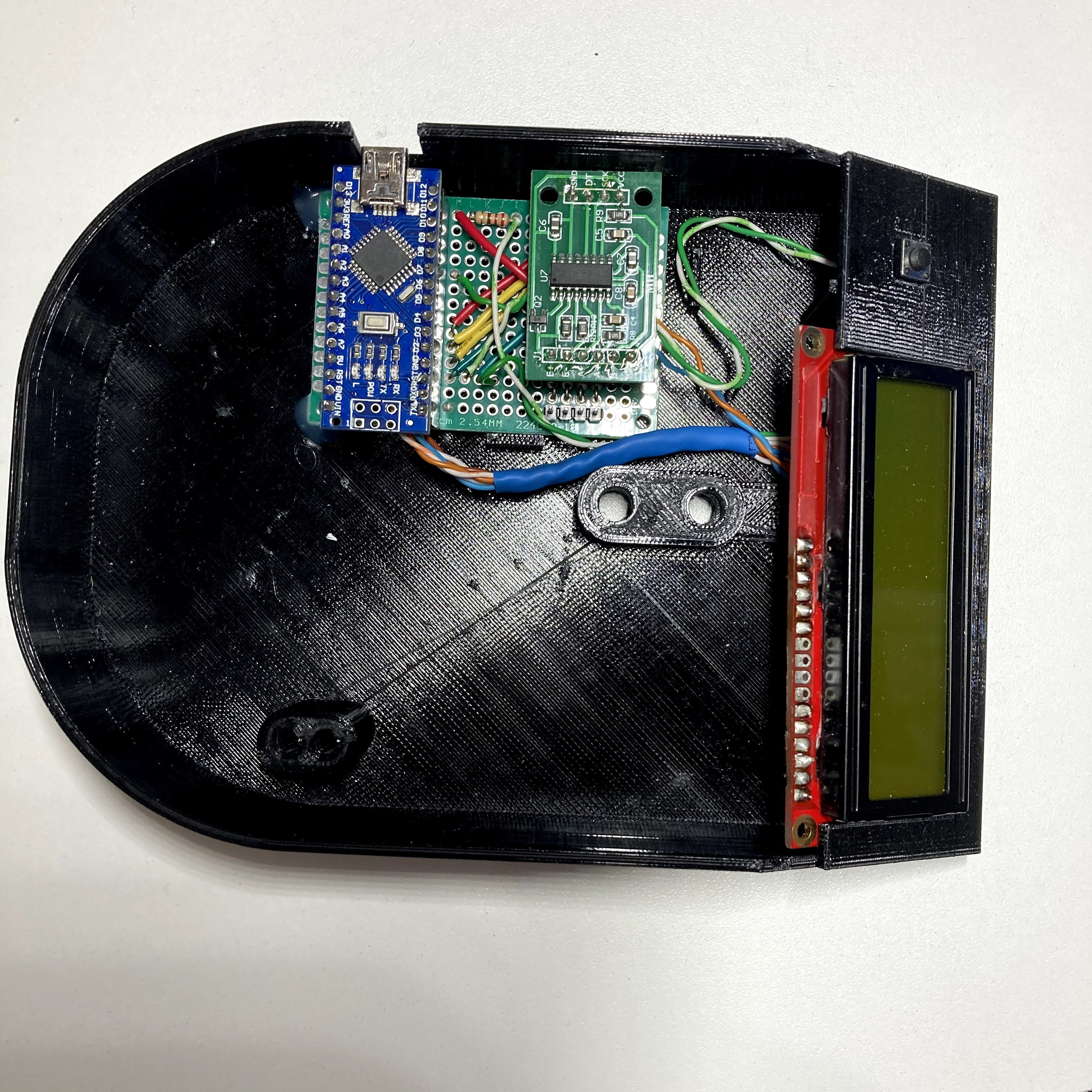
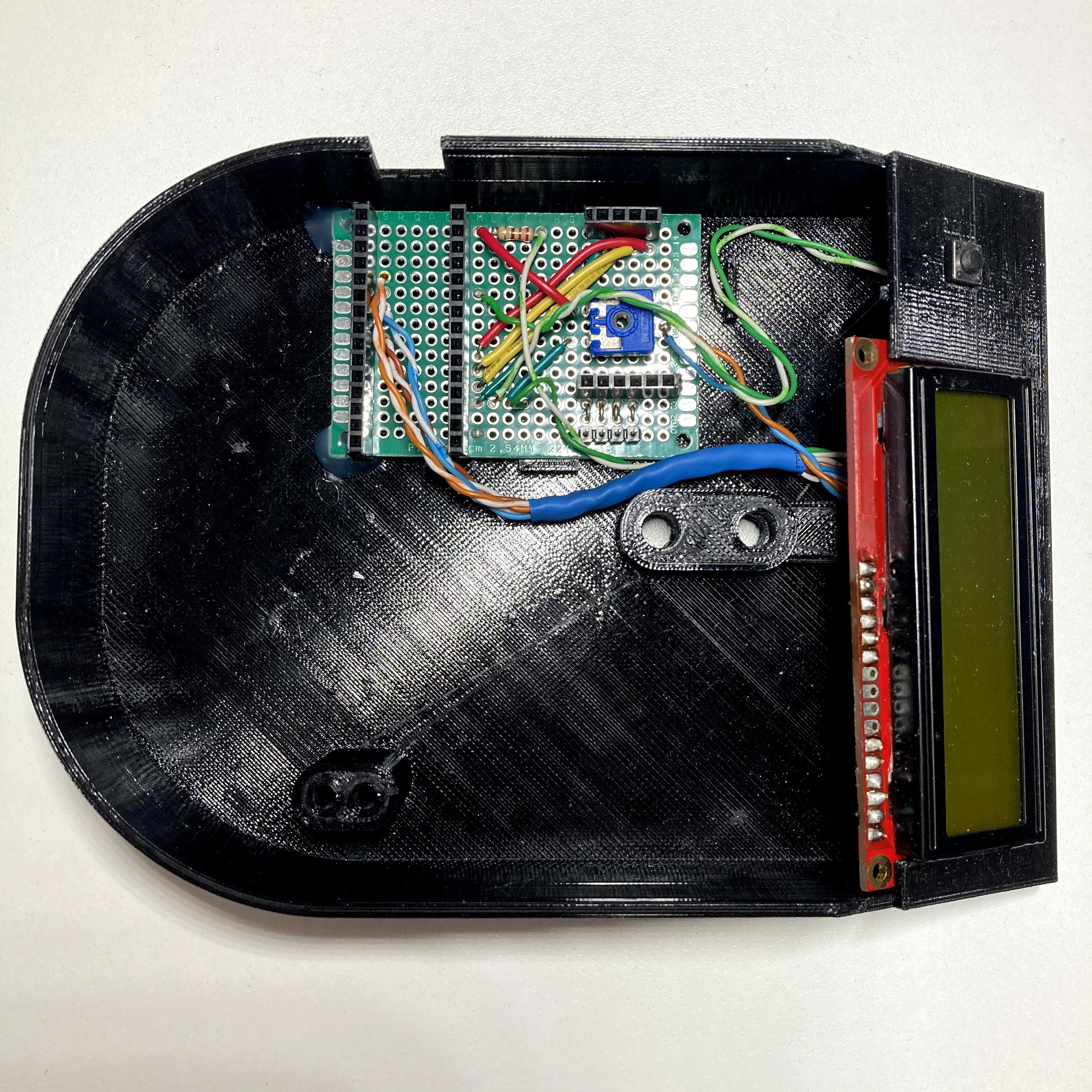
Required items
Section titled “Required items”- 4 x 6 cm solder breadboard
- 200 mm (8 in) lengths of twisted pair, as from Cat 5 cable:
- 2 x green / green-white
- 1 x blue / blue-white
- 1 x orange / orange-white
- 1 x brown / brown-white
- 1 x blue / orange
- 22 AWG solid-core wire:
- 2 x 40 mm (1.5 in) yellow
- 1 x 20 mm (1 in) green
- 3 x 30 mm (1.25 in) green
- 1 x 40 mm (1.5 in) green
- 1 x 25 mm (1 in) red
- 1 x 45 mm (1.75 in) red
- 4 x 8 mm (0.25 in) bare
- 220 ohm resistor
- 10 kohm trimmer potentiometer
- Female header pins: 2 x 15-pin, 1 x 6-pin, 1 x 4-pin
- Male header pins: 1 x 4-pin
- 16 x 2 LCD
- Normally-open push-button
- Heat shrink, diameter x length: 1 mm x 45 mm (cut in half), 3 mm x 45 mm, 5 mm x 45 mm
Note: the header counts here differ from the paper’s Table 1, which lists
the parts of an earlier build; see
bom/.
Install the header pins
Section titled “Install the header pins”Solder the headers onto the breadboard as listed.
| Female header | Breadboard position |
|---|---|
| 15 x 1 | T0-T14 |
| 15 x 1 | N0-N14 |
| 6 x 1 | A4-F4 |
| 4 x 1 | B14-E14 |
| Male header | Breadboard position |
|---|---|
| 4 x 1 | C1-F1 |
Finally, use the four bare pieces of wire to connect the four male header pins to their four neighbours on the 6 x 1 female header. The other two receivers on that header (A4 and B4) are not used; they are there to locate the HX711 amplifier.
Install the potentiometer
Section titled “Install the potentiometer”A potentiometer has three pins: 1 (fixed), 2 (wiper) and 3 (fixed). Here pin 1 is ground, pin 2 the output and pin 3 Vcc.
- Pin 1 (GND): F7
- Pin 2 (wiper): B8
- Pin 3 (Vcc): F9
Install the jumper wires
Section titled “Install the jumper wires”This uses all the 22 AWG solid-core wires except the three 30 mm green ones.
The jumpers connect pins that are already installed to other installed pins:
each is run to a pad next to the pin of interest, and its extra lead is bent
over to touch the solder on that pin so the two can be soldered together. In
the table, each end is written pad to insert into: pad to solder to.
| Wire | End 1 | End 2 |
|---|---|---|
| Green 40 mm | E13: E14 | M3: N3 |
| Yellow 40 mm | D13: D14 | M4: N4 |
| Yellow 40 mm | C13: C14 | M5: N5 |
| Red 45 mm | B13: B14 | M6: N6 |
| Green 20 mm | L3: M3 | G7: F7 |
| Red 25 mm | M14: N14 | G9: F9 |
| 220 ohm resistor | L14: M14 | I14 |
Note: all three firmwares power the LCD from pin D5 (lcd_vcc = 5 in
mass-scale.ino, LCD_VCC = 5 in the 2020 sketch’s Pinouts.hpp). By this
guide’s pad numbering (GND at N3, D2 at N4, D8 at N10), D5 is pad N7 and N14 is
D12. The red 25 mm wire and the 220 ohm resistor share pad M14 and feed the
potentiometer’s Vcc (F9) and I14. If that node is the LCD’s supply, it belongs
on N7, not N14. Check against your build before soldering.
Wire the button
Section titled “Wire the button”Connect one of the green / green-white twisted pairs to the pins of the button, covering the exposed wire with the two pieces of 1 mm heat shrink. The other ends are attached to the breadboard last, because the button has to be installed in place in the scale’s housing.
Wire the LCD
Section titled “Wire the LCD”The LCD has 16 pins, numbered 1 (VSS) to 16 (LED-), as in the schematic. It is wired with all the remaining twisted pairs and the three 30 mm pieces of green solid-core wire.
- Take the green / green-white pair. Connect one end of all three solid-core wires to one end of the green wire, making a three-wire pigtail, and cover the joint with the 3 mm heat shrink. This grounds the LCD.
- Connect the three pigtail ends to pins 1, 5 and 16 of the LCD, and the matching end of the green-white wire to pin 15. The other end of this pair will go to the board to power the backlight.
- Brown / brown-white pair: brown to 14, brown-white to 13.
- Blue / blue-white pair: blue to 12, blue-white to 11.
- Orange / orange-white pair: orange to 6, orange-white to 4.
- Blue / orange pair: blue to 3, orange to 2.
- Green / green-white pair: green to K3: L3, green-white to H14: I14.
Without shrinking it, slip the 5 mm heat shrink over the four single-colour twisted pairs (leave the blue / orange pair free). Do not shrink it yet. It will hold the wires together and out of the way of the load cell once the board is complete.
Now attach the LCD to the breadboard, keeping in mind how the wires will lie in the housing (dry-fit before cutting to length). The notation is the same as for the jumpers: insert into the first pad, solder to the second. Soldering the pad the wire is inserted into as well gives extra strength.
- Blue / orange pair: blue to A8: B8, orange to F10: F9.
- Brown / brown-white pair: brown to S6: T6, brown-white to S7: T7.
- Blue / blue-white pair: blue to S8: T8, blue-white to S9: T9.
- Orange / orange-white pair: orange to S10: T10, orange-white to S11: T11.
With the wires in place and lying properly in the housing, heat the heat shrink to fix their shape and keep them off the load cell.
Finish installing the button
Section titled “Finish installing the button”This is the most awkward step, which is why this twisted pair has extra length.
- Feed the green / green-white pair from the button through the hole in the face of the housing.
- Connect green to J3: K3 and green-white to M10: N10.
Install the board and LCD
Section titled “Install the board and LCD”If not already done, seat the LCD in its slot in the housing, routing its wires around the load-cell boss. If any wire rests against the load cell, reliable measurements are impossible. Seat the breadboard so that the Nano’s USB port will be reachable through the slot in the base; if it is not held tightly, hot glue on two or three corners secures it.
Finishing up
Section titled “Finishing up”Put the Arduino Nano onto the two 15 x 1 headers and load a sketch that drives only the LCD and prints something on it. (With the scale firmware, comment out the initialisation of the balance, load cell and HX711 for this step, since the HX711 is not installed yet and the firmware would wait for it.) The LCD is now powered, but probably shows nothing legible: turn the potentiometer with a screwdriver until the text is clearly visible. This sets the contrast and does not need adjusting again.
Power down, plug the HX711 into the other female header, and install a load cell, connecting it to the four male header pins.
The scale should now work. For the mechanical assembly and the load-cell
mounting, see Section 2.3 of the paper in
paper/, and for
using the scale, operation.md.